Written By: Michael A. Hosch, P.E.Director of Product Development
The handling of pharmaceutical / medical products and medical product assembly has unique requirements. They are generally very small. They are often made of plastic, very light and can be fragile. Parts and assemblies of this type include vials, RV’s, syringes and catheters as can be seen in Figure 1.
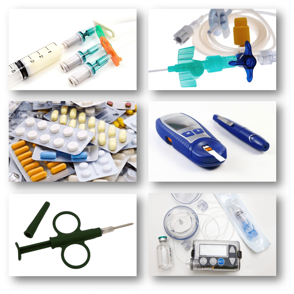
Figure 1 – Typical Pharmaceutical / Medical Products
1. Part End Transfer
Since the parts are so small the ability to transfer them from one conveyor to the next can be problematic. Parts are often less than 1″ in size, therefore requiring a roller diameter much less than 1″. Typical conveyors have rollers 1 ¼” or larger. These are simply too large to be practical as seen in Figure 2. An alternative method of transfer shown in Figure 3 is called waterfall transfers. This is accomplished by placing the roller of one conveyor over the next. While this does transfer the part it does not maintain product orientation due to the drop in height and can cause product damage from the free fall. In addition, parts like vials simply cannot use this method.
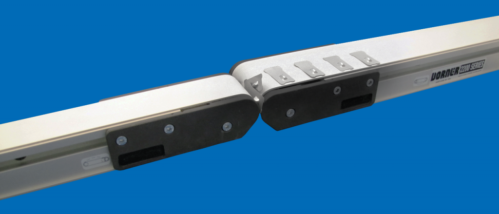
Figure 2 – Small Part End Transfer

Figure 3 – Small Part Waterfall Transfer
2. Part Side Transfer
If a part cannot be transferred off the end of a conveyor the alternative method is to transfer off the side. If the belt edge is close to the conveyor frame you can then transfer small parts. This is illustrated in Figure 4. However, most conveyors have their bearing housings on the outside of the conveyor frame. Even if the housing is staggered and minimized to ½” or less, as is commonly done, this still does not allow for the transfer of very small parts or vials.

Figure 4. Small Part Side Transfer
3. Conveyor Belt Flatness
Typical operations performed in these applications include vision inspection, filling, robotic pickup, etc. All of these require that the part sit flat on the conveyor belt. Since the part itself is so light it does not have the weight to force the conveyor belt flat. It will simply follow the surface flatness of the belt. Belting used for small end rollers needs to be very thin. These thin belts have a tendency to curl when placed under tension. This belt curl causes the light part to not lay flat causing problems for the automation process.
4. Size of the Conveyor
Typically the floor space an engineer is given for an assembly machine is relative to the product being assembled. Let’s be honest, it takes more room to assemble a car than it does an IV bag. Since the parts used are small and the end product is small, then it holds true that the room you are given to accomplish the tasks is small. There is simply no room in the machine for oversized conveyors and the associated motors and drives that go with them. This also generates a new challenge for the engineer. Since the machine is small, the distance between operations is short. Therefore the conveyor transporting the product from one operation to the next is short, often less than 12″ long. Conveyor manufacturers simply do not offer conveyors this short because the room needed for their end rollers doesn’t allow it and the fabrication of a belt that short is difficult.
The combined result of all these challenges has left the design engineer with two alternatives. One, design and build your own conveyor that meets these requirements. This is often expensive, but most importantly takes the engineer away from the task they were given, determining the method to fabricate or assemble the medical part. The second method is to use an alternative technology such as a slide rather than a conveyor. The issue here is a simple cost effective conveyor is what was needed but because it couldn’t”t be found or sourced, a more expensive and possibly less effective solution had to be used. Ultimately what is needed for this application is a miniature conveyor.
Obviously, the creation of a miniature conveyor is not as simple as taking the design of the standard conveyor and shrinking them by a factor of two. There are several challenges that the conveyor manufacturer faces including; bearing life as a result of small bearings, small component strength and durability, consistent short belt fabrication and effective use of product space. Added to these are the unique needs of the customer including small end rollers, side part transfers, and very flat belting. In addition, the conveyors are often inside a machine surrounded by other equipment. Therefore maintenance, such as belt tracking and belt change must also be considered.
The conveyor shown below is the result of a product development effort to solve the problems facing design engineers for pharmaceutical/medical product automation. It has two belt drive options, an End Drive option as shown in Figure 5, and a Mid Drive option shown in figure 6. The Mid Drive option removes the drive motor and mechanism from the end of the conveyor, opening it up for ease of product transfer and machine interface.

Figure 5 – Miniature End Drive Conveyor

Figure 6 – Miniature Mid Drive Conveyor
The conveyors have end rollers that are only 5/8″ in diameter. When placed together, as shown in Figure 7, miniature conveyors can transfer a product as small as 7/8″ in diameter. In addition, both models can be equipped with 5/16″ dual end rollers. When placing these versions together with a product as small as 5/8″ in diameter can be transferred.
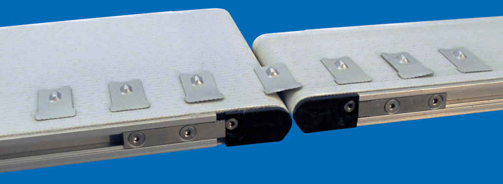
Figure 7 – Miniature Conveyor End Product Transfers
The miniature conveyor shown in Figure 8 incorporates new technology that allows small products to be side transferred. The end roller support is completely flush with the side frame of the conveyor. When two conveyors are staggered for side transfer there is only ¼” from belt edge to belt edge. This allows side transfer of parts as small as ½” in diameter. The technology providing this feature is called stepped T-slot technology. The T-slot as shown in Figure 9, has a stepped clamping surface. By use of this technology the head plate can still be extended in and out from the main conveyor frame, for belt tensioning or belt tracking, but no longer protrudes beyond the limits of the frame as is common in most belt conveyor designs.
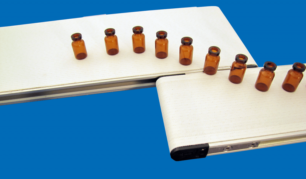
Figure 8 – Miniature Conveyor Side Product Transfers

Figure 9 – Stepped T-Slot
There is one technology that is the driving force behind miniature conveyors enabling the components to be so small. This technology is the pinch drive mechanism. The pinch drive is incorporated in both the End Drive conveyor and the Mid Drive conveyor and allows the conveyor to run with almost no belt tension. Typical belt conveyors run under high tension. Tension is needed for the drive roller to have enough traction to drive the belt. However, it is this tension that causes bearings and conveyor rollers to be oversized to handle the load. A miniature conveyor simply is not large enough to handle typical belt tension. The purpose of the pinch drive is to force the conveyor belt against the drive roller giving it driving traction without the use of tension. This is shown in Figure 10. The patent pending Mid Drive conveyor has two pinch rollers. Each spring loaded against the drive roller. This configuration allows the belt to be run in either direction and only requires enough belt tension to lay the conveyor belt flat. Since over-tensioning the belt is not required the belt lays flatter which is needed for light weight medical components. In addition, since the pinch drive does not need tension to drive, there is no need for belt take-up or belt stretch maintenance.
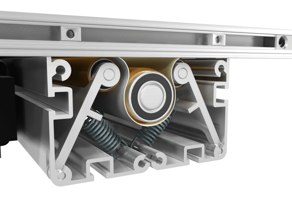
Figure 10 – Pinch Drive Mechanism
The only potential disadvantage to the pinch drive mechanism is it adds complication to the belt change process. Since the belt is now woven between two or more rollers these rollers must then be removed to change or maintain the conveyor belt. This miniature conveyor design also incorporates a patent pending two-half drive construction to aid this need. This construction, as shown in Figure 11, allows the top half of the drive module to be separated from the lower half. This is done by simply removing a few screws. With the lower half of the module, which contains the pinch rollers, removed the conveyor belt is now free to be removed from the side of the conveyor. This process is substantially quicker than is typically experienced with traditional center drive tension type conveyors.
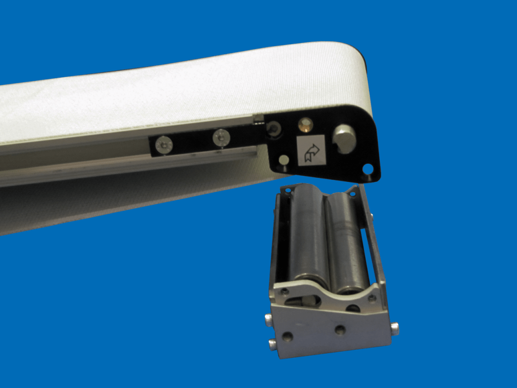
Figure 11 – Belt Removal
The invention of the miniature conveyor gives greater flexibility and options to design engineers in the handling of pharmaceutical / medical products and medical product assembly. It provides smoother product transfers, takes up less space and is Class 100 verified* for cleanroom environments.
The miniature conveyor illustrated in this paper is the Dorner Mfg. Corp. 1100 Series conveyor. For more information on the 1100 Series conveyor and other innovative Dorner products see www.dornerconveyors.com.
*To verify clean room requirements, an unloaded base conveyor was tested and did not generate particulate that would be beyond the specified standards. However, the verification does not provide assurance that any or all applications will meet this requirement. Application testing is recommended to ensure clean room standards are being met. Dorner takes no responsibility in the clean room performance of the final conveyor or application.